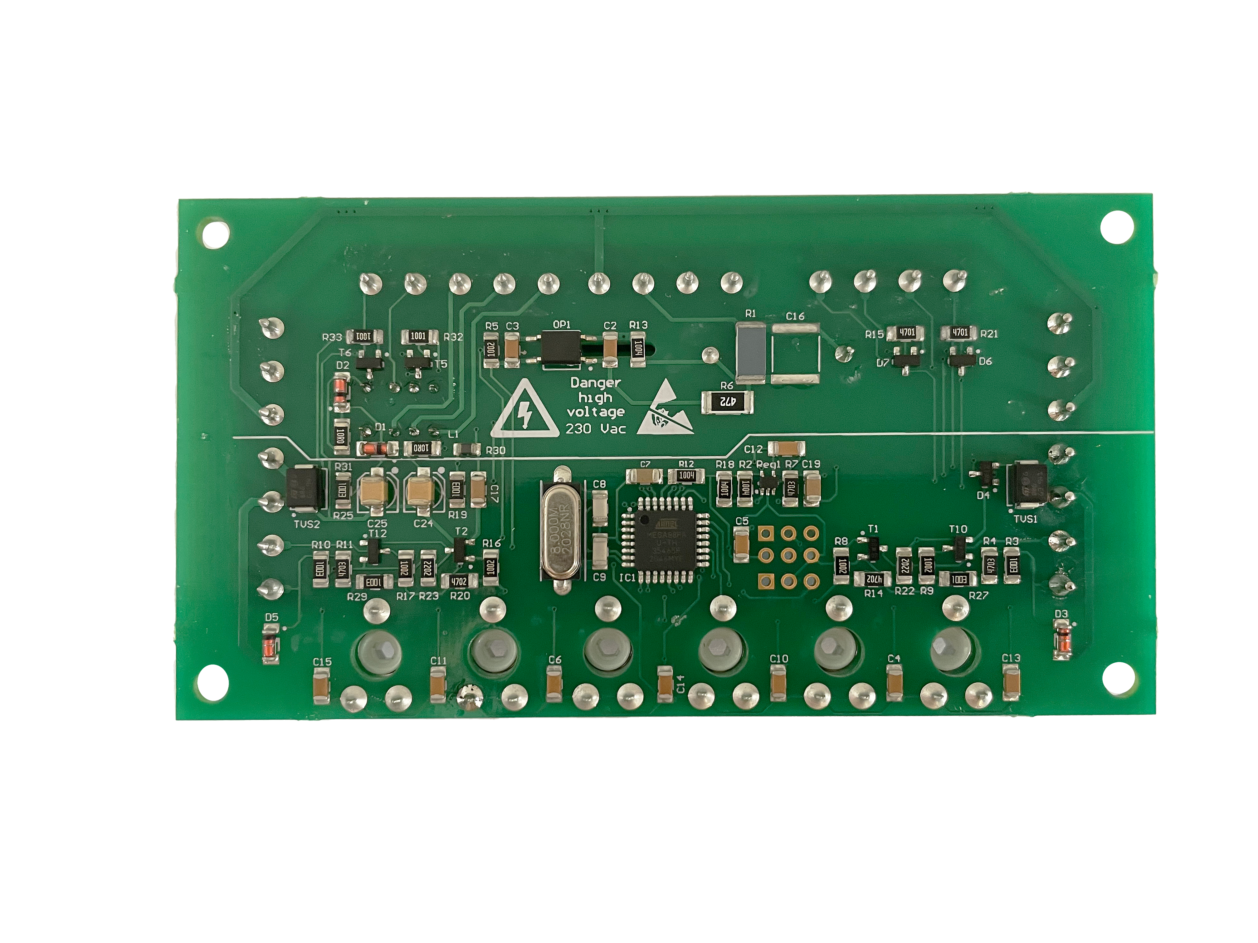
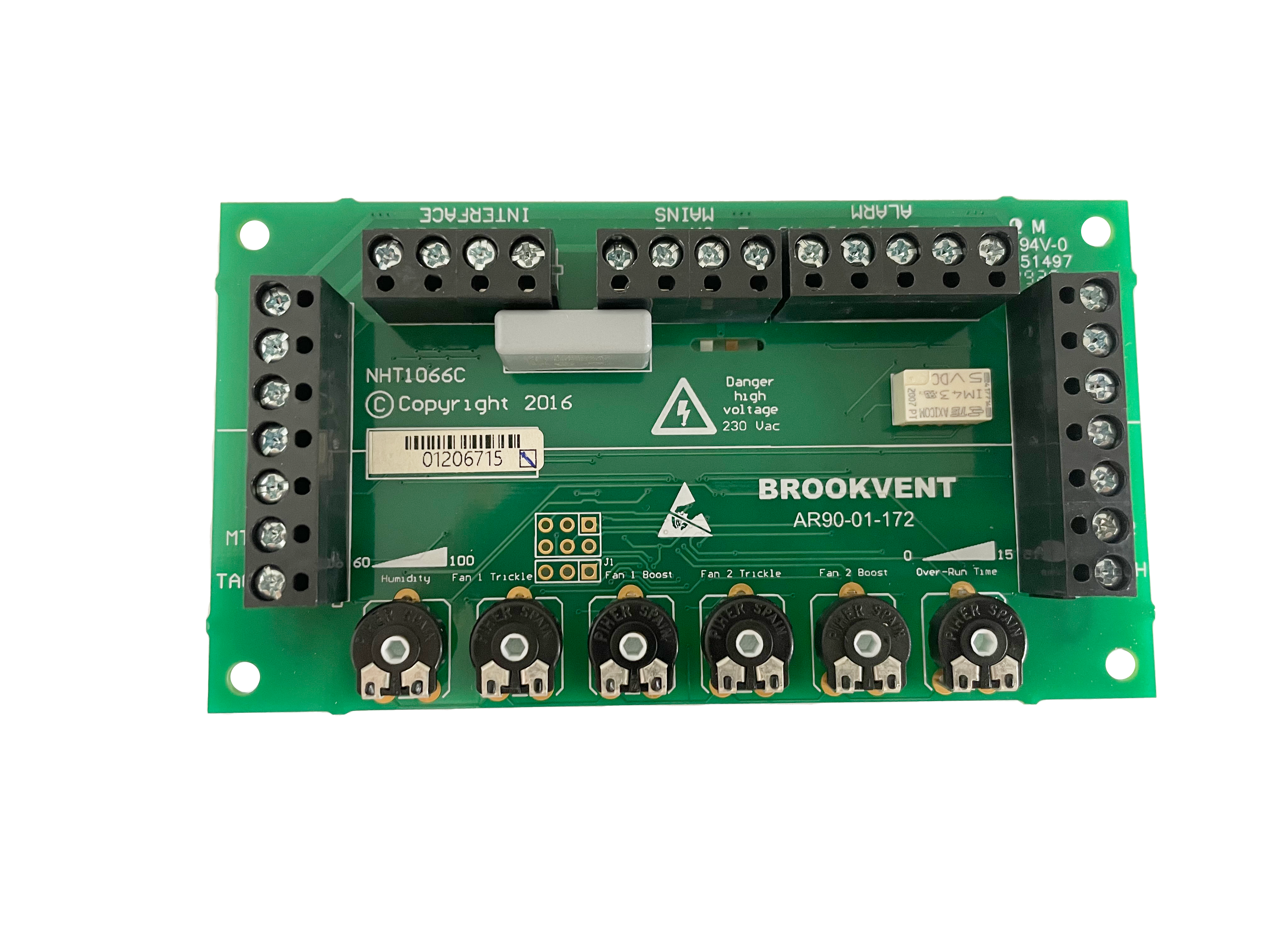
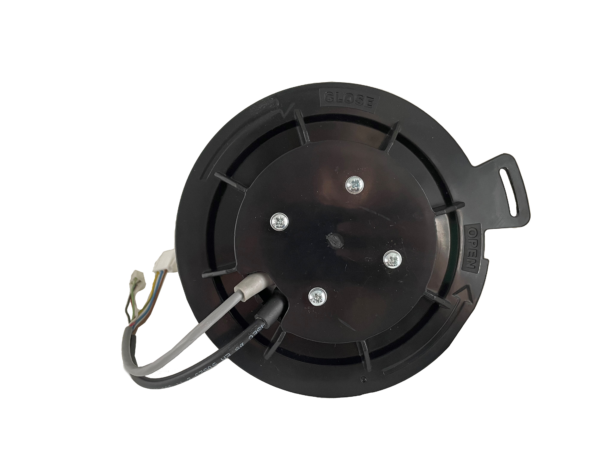
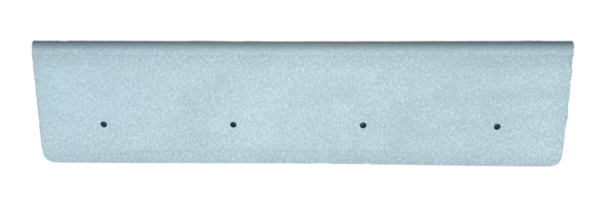
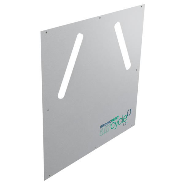
Brookvent Aircycle 1.3/1.3+ Individual Fan Kit
The Aircycle 1.3 heat recovery system has a very straight forward fan replacement process should the unlikely event of a failure. Product Code: AS 90-09-901
The Step Process:
Step 1. Isolate the unit from the mains and ensure all supply circuits are disconnected.
Step 2. Unscrew the front cover (4 No. screws) and remove the cover.
Step 3. Unplug the two leads from the fan.
Step 4. Unscrew the locking screw on the fan mount.
Step 5. Turn the fan mount anti-clockwise to the line marked on the fan case and then pull straight out.
Step 6. Place the new replacement component assembly in the case, lining it up with the line marked in the case. Push inward until flush with the front case and then turn clockwise to tighten.
Step 7. Refit the locking screw and connect the cables
Step 8. Re-fit the front cover and secure with the screws.
Step 9. Power the unit on at the isolator and ensure any supply circuits are reconnected. The unit will not need to be re-commissioned as the controller will hold the settings.
If you have any questions regarding this procedure, please get in contact with the office on 02890616505 or hello@brookvent.co.uk
https://brookvent.co.nz/product/aircycle-1-3-house-ventilation-system/
